Click here to see all articles in this series: DIY Wood Steering Wheel
Machining the Halves
Once the two hexagons were cured, it was time to cut. I own a hand held Porter Cable router. Not owning a router table, nor desirous of buying one, I made a suitable router table base specific to this task. For a base I bought a $6 section of melamine shelving stock, 12 x 36 x 3/4 inch, at Home Depot. I started by drawing a center line on the board; the center line would be used for locating the router bit as well as the center points for the various radii to cut the groove, ID, and OD. After drawing the center line I used a 2 inch circle cutting bit to cut a large hole for the router bit. Figure 14 shows the home made router table with the router underneath.
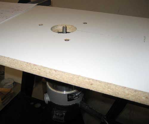
Figure 14: Homemade router table
I don't have an extensive collection of router bits, so from the few I own I used the following for making the cuts:
- 3/8 inch diameter straight cutting bit for the center groove
- 1 inch diameter straight cutting bit for the OD and ID
- 1⁄2 inch round over bit for (do I need to say it?) rounding over the corners on the OD and ID
Before making any cuts on the hexagon blanks, I needed to make a center bar for each. The center bar is necessary so that I can mount a pin at exactly the center of each blank. The pin is then placed into the hole on the router table. This center pin allows the part to spin around the stationary router bit to make the perfectly circular cuts.
Once I had the center bar and center point on each blank, I made layout marks for the groove centerline, the OD, and the ID. I also made some marks for rough cuts that I could make with a jigsaw. There's no need to cut all the scrap away with the router, especially on the ID and OD, so making a rough cut is the logical way to go. Note that I didn't have a compass large enough to draw the diameters so I made a mini-story pole with the appropriate radii specific to this project. Figure 15 shows a hexagon blank with center bar attached; see also the story pole (homemade compass) used for layout. Figure 16 shows a hexagon blank with the rough cut-out lines, note the ID is not a complete circle.
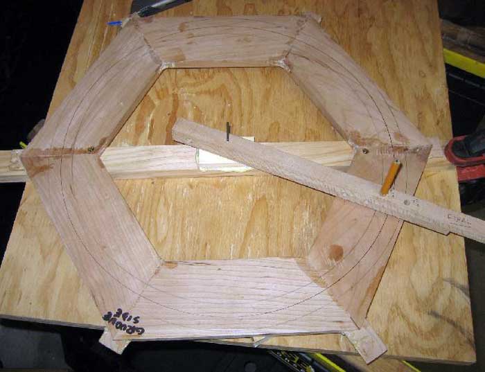
Figure 15: Hexagon blank with center bar showing homemade compass to draw layout lines
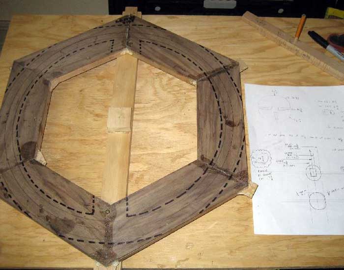
Figure 16: Hexagon blank showing layout of rough-cut lines (dashed lines)
Based on my design and my 3/8 in diameter straight cutting router bit, the first center point is at 7.375 inches on my router table. Note that I do not have a plunge router so I had no ability to plunge the bit into the wood. Because of this, I had to do the slightly risky move of making a plunge cut by dropping the wood onto the spinning router bit. Needless to say, hold onto the wood blank securely when making such a cut. Also, I didn't try to rout the full depth in a single pass. I made several cuts of 1/8 inch or less on a single pass. If I was going to make more than one steering wheel, I would probably look into a different solution as making plunge cuts seems to give the highest opportunity for error. In the blank for the front (driver facing) half of the wheel, I cut the groove to a depth of 3/8 inch. In the blank for the back half of the wheel, I cut the groove to a depth of 3/16 inch. Figure 17 shows the two wheel halves after the groove has been machined. The half on the right with the darker wood is the front half with the walnut veneer.
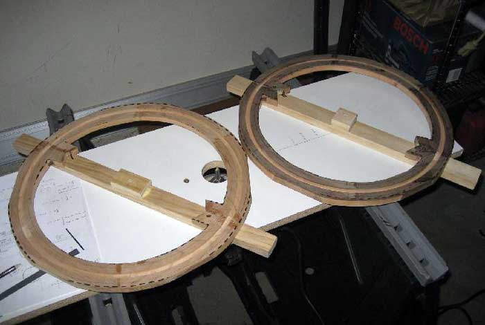
Figure 17: Groove cut into both hex blanks (rough cut was also complete at this point)
Before progressing any further, I did a quick test fit of the steel wheel into the grooves; see Figure 18 below.
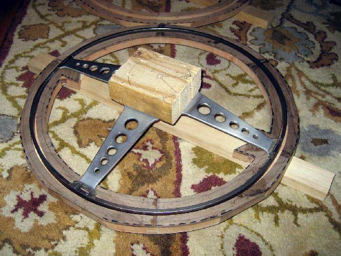
Figure 18: Test fit of steel rim into groove
The next cut to be made with the router is the OD. I used a 1 inch diameter straight cutting bit for this cut. Based on the design, the OD is to be 15-3/4 inch. Thus, the center point to cut the OD on my router table is set at 8.375 inches. This cut was also made in several passes removing approximately 3/16 in a pass. To avoid having to make a plunge cut, I used a block plane to reduce one edge to the proper radius. I felt this was a safer strategy and would reduce the risk of damaging the wood. I started to become a bit anxious with each new cut because any errors would likely necessitate starting over! Figure 19 shows a close up of the front half after using a plane to remove material to the OD line.
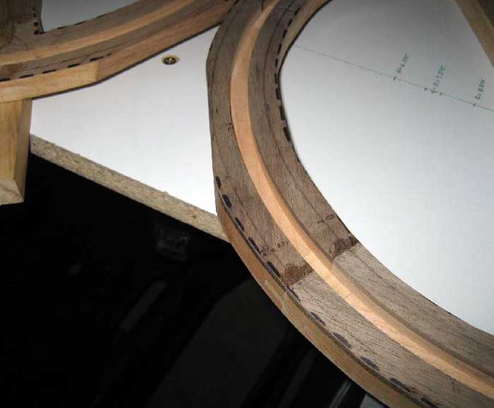
Figure 19: One area of OD shown cut to size using a plane to avoid a plunge cut with the router
As before when cutting the groove, I cut the OD in multiple passes until complete. I cut completely through the wheel blank and just into the center bar. Figure 20 shows the front wheel half after completion of the OD; look carefully and you'll notice the small amount of material removed from the center bar just to the left of the wheel. The picture shown is slightly out of sequence because it also shows the cut of the ID cut begun; cutting the ID is discussed in the following paragraphs.
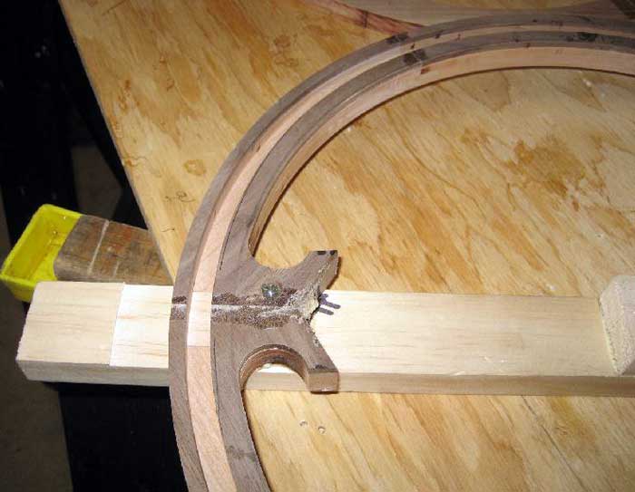
Figure 20: OD shown cut to full depth
Cutting the ID was slightly more difficult because it was not simply a matter of spinning around in a complete circle – if you cut the ID completely, then the center bar could no longer be connected to the wheel blank. The key was to cut the ID completely only when I knew I would no longer have to spin the wheel blank on the center pin. The ID was to be 13- 3/4, so I simply made a new center pin location on my router table. The new location was at a radius of 6.375. Unlike the OD, I had to slide the wheel blank into the spinning router bit to get to a start point. This was a bit risky because any slip would likely damage the wood blank, but not having a better solution at hand, I took the chance. I did this as follows: I'd turn on the router, place the wheel blank on the table with the bit inside of the ID, then slowly and carefully slide the wheel into the spinning bit until I was able to push the centering pin into the hole on the router table. As before, I removed only about 3/16 in a pass. However, unlike the process used to cut the OD, when cutting the ID I made two cuts of less than 180 degrees each – I cut up to the center bar and then stopped. This was to preserve the center bar and centering pin as long as possible. Figure 21 shows the ID cut to full depth but not around the entire circumference. I cut only up to the center bar; the dark areas on the wood are burn marks which resulted from moving the part too slowly against the spinning router bit.
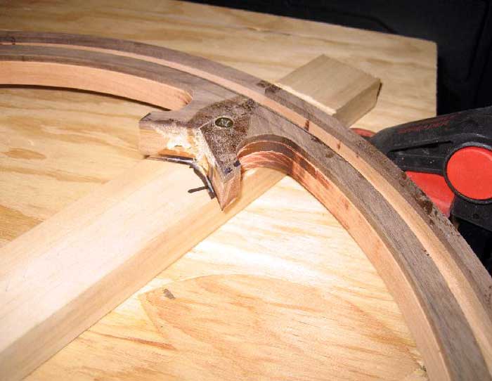
Figure 21: ID shown cut to center bar only
Once I cut the full depth of the ID, I again checked to make sure everything was going as planned before cutting the last bit of the ID and freeing the wheel blank from the center bar. If you look closely at the Figure 21, you'll notice a screw holding the wheel blank to the center bar. Obviously I couldn't complete the cut with that screw in place so I had to change the way the wheel blank was held to the bar. I removed the bar and carefully applied glue only on the area inboard of the ID of the steering. See Figure 22 below; the blue arrow shows the screw that was originally used to hold the wheel half to the center bar and the green rectangle shows the area in which glue was used between the wheel blank and the center bar. The screw was used to hold things in place while the glue cured; I removed the screw before cutting the ID completely.
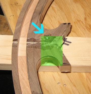
Figure 22: Detail showing holding screw and area to be glued
The idea was to use the router to cut almost all the way through the wheel blank but leave just a tiny bit of wood – approximately 1/16. Then use a coping saw to cut the remaining bit plus the center bar by hand. You could also use a jigsaw but since it was such a simple cut, I just used a hand tool. I wasn't too worried about a perfect cut at this area since it would be cleaned up during the next stage when I planned to round over the edges.
Now I had two blanks which were simply rings free of the center bar. The next step was to round over the corners of the OD and ID, but there was a bit of thinking to do before proceeding. The plan was to use a 1⁄2 inch round over bit which has a roller bearing against which you ride the part when making the cut. However, if I tried to cut only one wheel blank at a time, the bearing would not be able to ride against the part. The obvious and simple answer was to hold the two wheel halves together when making this cut. Simply taping the two halves together wasn't satisfactory since there would be some ability to have slippage between the parts. I decided I needed some sort of positive locating device to hold the two pieces in the correct orientation to one another. I chose a simple solution - I made three tiny steel pins by cutting a finishing nail. I then drilled three tiny holes in one wheel half into which I glued the pins. Then I carefully aligned the two halves together and gently squeezed by hand to make three indentations in the wheel half without the pins. This allowed me to drill three small holes in the correct location. Figure 23 shows one of the alignment pins – sharp eyed readers will note this picture is out of sequence because it shows the edges after the rounder over cuts.
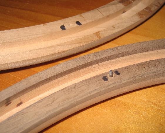
Figure 23: Detail of locating pin (wheel has three pins equally spaced)
Rounding the Steering Wheel
Moving along, I assembled the two halves together using the locating pins, and I used tape to hold the two halves together. By holding the two halves together, I had ample thickness to ride the part against the roller bearing on the round over bit. Figure 24 shows the two halves free of the center bars and taped together; the pins keep everything properly aligned so that only minimal clamping pressure from tape can be used satisfactorily. Figure 25 shows a close- up of the round over bit; notice the roller bearing which rolls along the wood being cut.
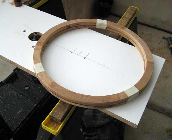
Figure 24: Two halves taped together ready to round over four corners (two OD and two ID)
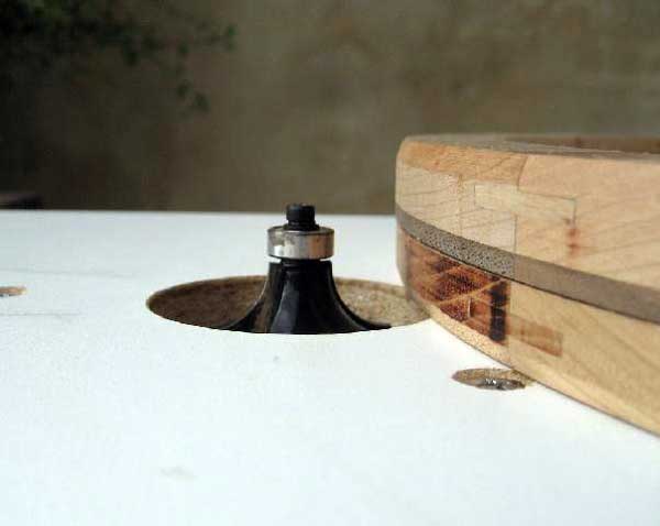
Figure 25: Close-up of round over bit showing how the bearing rolls against the wheel
As before, I didn't cut all the material in a single pass. I ended up doing things in three passes. To complete a single pass, I did things in two steps: 1) rout along the OD and ID everywhere EXCEPT where I had tape holding the halves together and 2) move the tape to three new locations and finish the cut. Then I simply raised the bit and repeated these steps until I had completed both the OD and ID on both sides. Figure 26 shows progress midway through the cutting – notice the radius isn't quite complete as you can still see a flat on the wheel rim.
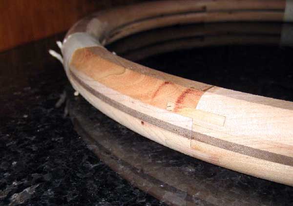
Figure 26: Round-over not quite complete at this point (notice flat still present on wheel rim)
When complete with the round over cuts, I was left holding a large wood bagel! With only some minor sanding, the cross section was about perfect. Figure 27 shows the wheel after the round over operation; I wiped the wood with a bit of alcohol to accentuate the grain and spline joint.
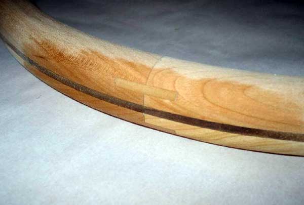
Figure 27: Round-over complete


your help, perhaps one day will come and be ready for Spring! Thanks for your detailed and
documented explanation of hoe to get 'er done!
you.
Now to find a steering wheel on Ebay for the progect.
Any project need a plan and a starting point. Reading this article is a great start.
Can you tell me what you did to the metal? It looks so shiny and pretty.. I am trying to restore mine (I have that same one with the foam) I just removed the surface rust, but the metal looks like stained. Any help is appreciated!
morris minor wheel....
morris minor wheel....
project instructions but with a different steering is it possible to
cut and weld peices so that it becomes a quick release because the
steering i have has round edges and the midle (center part)is for stock
cars... need your help thanks
similar, but based on the original sprung/dished profile Minor steering
with a thinner rim. Though this would entail some unique difficulties of
its'own I think. One day. Great article.
me money!
Thank you!
process, use of a prototype, making the few tools you had work, and
general description of how and why you did what you did. Finished
product looks outstanding.
Want to leave a comment or ask the owner a question?
Sign in or register a new account — it's free