Click here to see all articles in this series: DIY Wood Steering Wheel
Fitting the Wood to the Steel
The next step was to fit the steel rim to the wood halves. There would need to be some minor cutting to fit the spokes. If you look closely at the steel wheel, you'll observe that the spokes are welded to the back edge of the wheel rim.
Because of this, only very minor cutting was required on the front half of the wood wheel. I simply marked the areas where the spokes would interfere with the wood and then used a Dremel rotary tool and hand chisel to carefully shave the wood as necessary. If you look closely at the following pictures, you can see where I marked and shaved the front wood blank to fit the steel rim.
Before showing the details to fit the spoke, it will make things more clear to first show one picture out of sequence. Figure 28 shows the finished design where the spoke is mostly fit into the back half of the wood rim. Only a small amount of material was removed from the front half to accommodate the slight angle of the spoke due to the dished design. The bulk of the wood removed to fit the spoke was taken from the back wood rim.
Figure 29 shows a detail image of the small amount of material removed from the front half of the wheel blank. Figure 30 shows how the spoke rests in front half of the wheel.
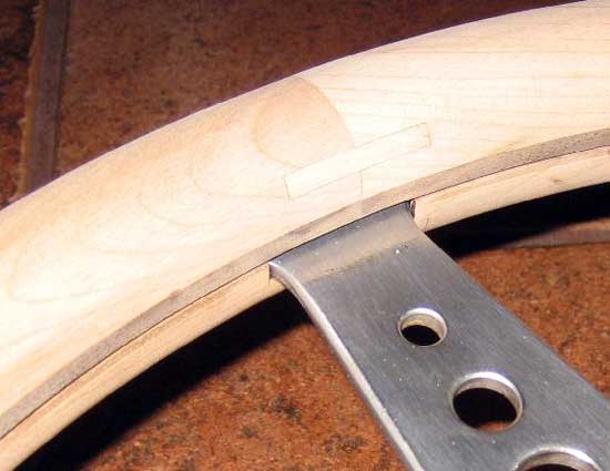
Figure 28: Finished fitting of spoke (note that the walnut layer is actually part of the front half)
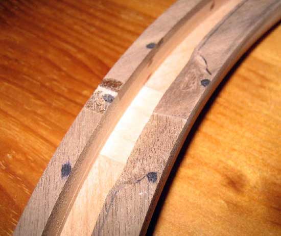
Figure 29: Detail of front half showing material removed for clearance with wheel spoke
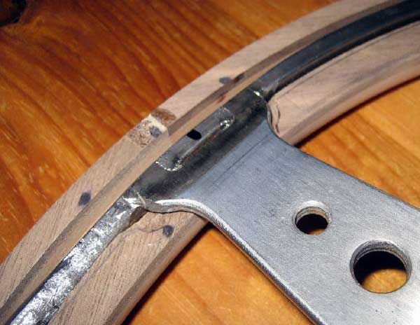
Figure 30: Detail showing spoke let into front half of wood rim
The back wood half would require more serious cutting to fit the spokes. Almost the full thickness of the spoke would have to be accommodated in the back wood blank so again I carefully marked the affected area and then used a router to remove approximately just under 3/16 inches of material. Figure 31 shows the wood removed from the back half of the wheel. I used a router with a 3/8 straight cutting bit to cut this area free hand. A sharp wood chisel would also suffice if doing this operation without power tools.
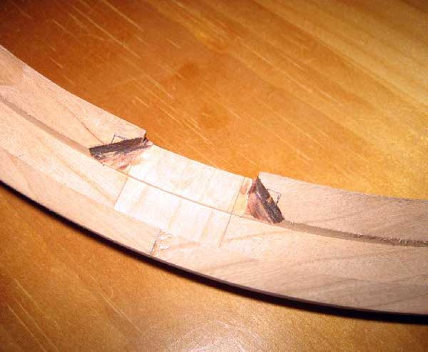
Figure 31: Detail showing material removed from back half of wood rim
As shown in Figure 32, things are pretty far along and it's actually looking like a steering wheel!
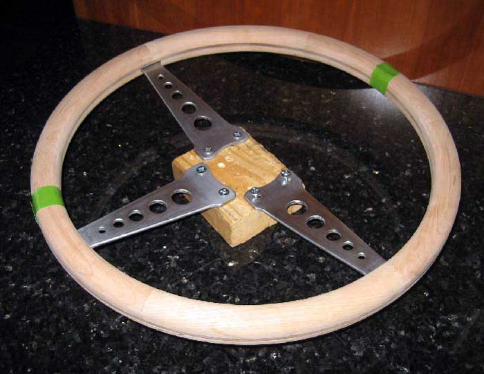
Figure 32: Steel spoke-rim subassembly completely fitted to wood rim
Making the Finger Grooves
I debated for a brief time whether to put finger grooves in the back of the wheel. I have seen plenty of examples of wood wheels and most have the grooves. The few I saw without grooves looked to be missing something to my eye, so the decision was made to put the grooves on my wheel.
I measured the old foam grip and measured the depth of each groove at about 3/32 inch and the spacing was approximately 1-1/8. Some quick math and I decided that I would put 40 grooves into the wheel which meant 9 degrees of spacing between each groove.
I made a paper template with the necessary layout. I pushed a pencil through the paper to make small holes through which I could mark the wood before making any cuts. Figure 33 shows how the paper template was placed over the wood rim to mark the location of the finger grooves. Make sure you cut the grooves on the correct side of the wheel otherwise you're likely to invent new curse words should you cut the wrong side of the wheel and be forced to start over!
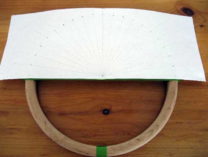
Figure 33: Layout template to mark finger grooves
Note that I ended up with only 37 grooves because I didn't put a groove at the location of each spoke, thus 40-3 = 37 grooves. A Nardi wheel that I studied didn't put the grooves at the spoke locations either, thus my decision to do the same.
The next issue was just how to cut the grooves. I suppose I could have used a router bit such as a "cove" bit, but I didn't have one and I didn't want to spend $35 for a one time tool. I looked around the garage and found that I had a good wood file with a circular profile of approximately 1-1/8 diameter. I made a few test attempts in my prototype pine steering wheel blank and the results were promising. Thus the decision was made to go the manual, hand-tool route. I wanted to ensure each groove was the same depth so I made a simple jig using two blocks of scrap wood. I cut these two blocks to be 3/32 shorter than the steering wheel thickness, and I fixed these blocks to my work surface. My plan was to simply file by hand at each mark and as soon as the file kissed the wood blocks the groove was complete. Figure 34 shows how the wood blocks were fastened to the work table to act as a jig when filing the finger grooves. This operation was quite simple and the results were outstanding if I do say so myself. It took less than one hour to file the 37 grooves. Figure 35 shows the wheel after all grooves were complete.
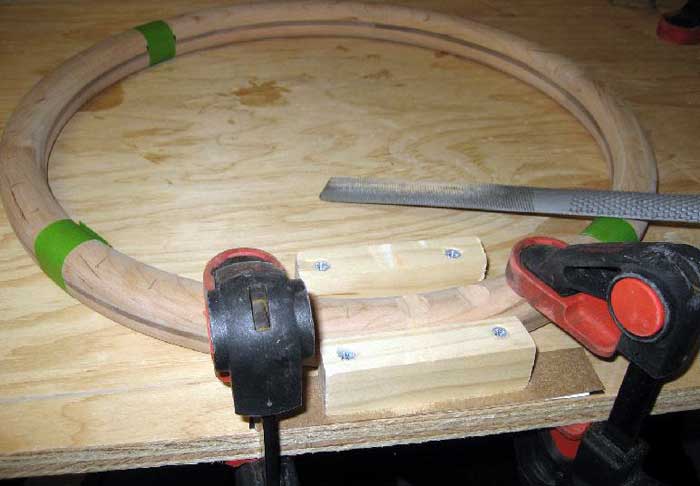
Figure 34: Configuration of jig to set depth of finger grooves
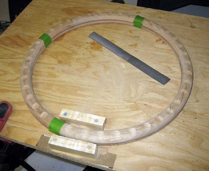
Figure 35: Finger grooves complete


your help, perhaps one day will come and be ready for Spring! Thanks for your detailed and
documented explanation of hoe to get 'er done!
you.
Now to find a steering wheel on Ebay for the progect.
Any project need a plan and a starting point. Reading this article is a great start.
Can you tell me what you did to the metal? It looks so shiny and pretty.. I am trying to restore mine (I have that same one with the foam) I just removed the surface rust, but the metal looks like stained. Any help is appreciated!
morris minor wheel....
morris minor wheel....
project instructions but with a different steering is it possible to
cut and weld peices so that it becomes a quick release because the
steering i have has round edges and the midle (center part)is for stock
cars... need your help thanks
similar, but based on the original sprung/dished profile Minor steering
with a thinner rim. Though this would entail some unique difficulties of
its'own I think. One day. Great article.
me money!
Thank you!
process, use of a prototype, making the few tools you had work, and
general description of how and why you did what you did. Finished
product looks outstanding.
Want to leave a comment or ask the owner a question?
Sign in or register a new account — it's free